There is a new codebase to log the UVR 1611 and 16x2. It is fully python based and very handy.
https://github.com/staircaseblog/uvr16x2logging
Donnerstag, 30. März 2017
UVR 16x2 Datenlogging mit CAN - Code online auf github
Soeben habe ich unter https://github.com/staircaseblog/uvr16x2logging einen neuen Logging Code für die UVR 16x2 und 1611 hochgeladen. Alles wurde supereinfach, übersichtlich und robuster. Es ist noch nicht alles drin, aber ich bin gerade ziemlich eingespannt und ich will niemand warten lassen.
Wer einen Raspberry mit CAN Adapter hat bekommt es in 10 Minuten ans laufen.
Viel Spass damit
Wer einen Raspberry mit CAN Adapter hat bekommt es in 10 Minuten ans laufen.
Viel Spass damit
Mittwoch, 15. März 2017
UVR 16x2 Daten Logging
Letzte Woche kam die neue Steurung und ich war einfach neugierig. Der existierende UVR 1611 Loggingcode läuft nun fast komplett in python statt in C. Im selben Atemzug wurden die Abfragen für die 16x2 gleich mit programmiert.
Die Zeit, Eingänge sowie Ausgänge mit den Bezeichnern werden abgefragt und die Auswertung erschließt sich größtenteils. Etwas Grübelei wird es wohl noch geben.
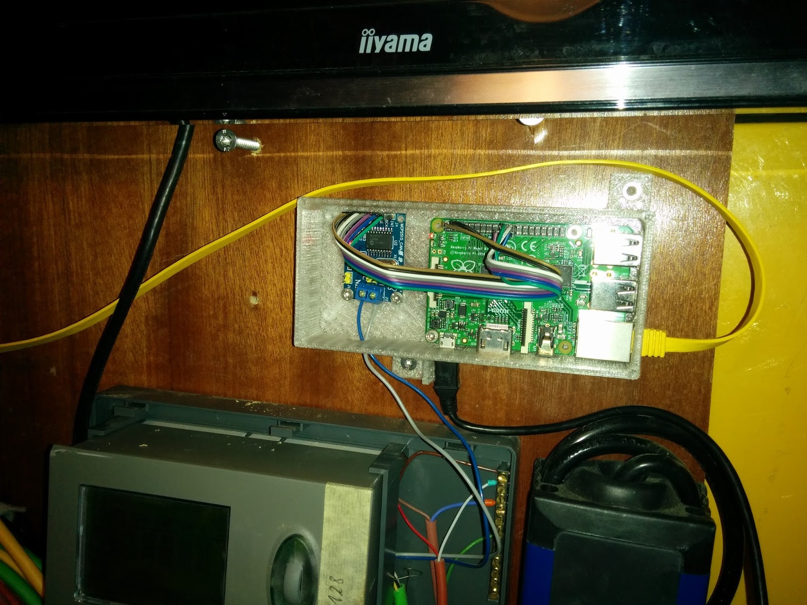
Das Bild zeigt die Spiellandschaft mit dem CAN Logger im praktischen Gehäuse, einer alten UVR 1611 und der neuen UVR 16x2 darunter. Ein BL-Net ist auch noch an diesem CAN Bus angeschlossen.

Es werden ggw. vom Logger keine NMT Nachrichten erzeugt, die anderen Netzteilnehmern das Vorhandensein bestätigt. Alle Anfragen an die SDOs werden vorher gebündelt und als kleine Gruppen abgesendet. Jeweils mit eigenen Verbindungsauf- und abbau. Sofern ein Fehler in der Gruppe auftaucht wird die betroffene Gruppe wiederholt.
Das funktioniert deutlich robuster als in der C Implementierung. Hier ein paar SDO request und die dynamische Gruppierung. Die Kodierung ist KnotenId_Index_Subindex. Die UVR 16x2 hat die KnotenID 4. Jede dieser kurzen Listen wird sequentiell abgearbeitet. Unter Index 8207 finden sich mit dem Subindex 0 bis 15 die Bezeichner der Eingänge im Unicode.
running batch:
['4_8207_7' '4_8207_6' '4_8207_5' '4_8207_4' '4_8207_3' '4_8207_2'
running batch:
['4_8207_0' '4_8207_9' '4_8207_8' '4_8207_13' '4_8207_12' '4_8207_11'
'4_8207_10']
Die Zeit, Eingänge sowie Ausgänge mit den Bezeichnern werden abgefragt und die Auswertung erschließt sich größtenteils. Etwas Grübelei wird es wohl noch geben.
Das Bild zeigt die Spiellandschaft mit dem CAN Logger im praktischen Gehäuse, einer alten UVR 1611 und der neuen UVR 16x2 darunter. Ein BL-Net ist auch noch an diesem CAN Bus angeschlossen.

Es werden ggw. vom Logger keine NMT Nachrichten erzeugt, die anderen Netzteilnehmern das Vorhandensein bestätigt. Alle Anfragen an die SDOs werden vorher gebündelt und als kleine Gruppen abgesendet. Jeweils mit eigenen Verbindungsauf- und abbau. Sofern ein Fehler in der Gruppe auftaucht wird die betroffene Gruppe wiederholt.
Das funktioniert deutlich robuster als in der C Implementierung. Hier ein paar SDO request und die dynamische Gruppierung. Die Kodierung ist KnotenId_Index_Subindex. Die UVR 16x2 hat die KnotenID 4. Jede dieser kurzen Listen wird sequentiell abgearbeitet. Unter Index 8207 finden sich mit dem Subindex 0 bis 15 die Bezeichner der Eingänge im Unicode.
running batch:
['4_8207_7' '4_8207_6' '4_8207_5' '4_8207_4' '4_8207_3' '4_8207_2'
running batch:
['4_8207_0' '4_8207_9' '4_8207_8' '4_8207_13' '4_8207_12' '4_8207_11'
'4_8207_10']
Freitag, 10. März 2017
UVR 16x2 Cabled and Logging
I put the 16x2 into the network at address 4 and applied the concept to establish a connection in the same way as with the 1611. Time and date are reliably logged. On the weekend the other in- and outputs are implemented.
On the same network is an old 1611 and a BL-Net. I wrote earlier that the BL-Net is not of any use to visit the 16x2. Also, i havent found a screen to attach the remote screen of the 1611.
Stay tuned. I am so hungry now. I think i will make myself a Okonimiyaki - a kind of slow cooked pancake with bacon and cabbage in. I deserve it.
TA UVR16x2 Daten Logging - erste Schritte
Das Setup steht soweit und die Uhrzeit/Datum kommt von der 16x2 direkt in die CAN-Logger Software. Die Objekt_IDs sind andere als bei der 1611 und es gibt zu jeden Ein-/Ausgängen mehr Zusatzinformationen.
Als nächstes kommen die Ein-/Ausgänge dran.
Als nächstes kommen die Ein-/Ausgänge dran.
Donnerstag, 9. März 2017
Case for the UVR CAN Data Logger
I was sick of the cable salad. Becaus we have a 3D Printer now i did some cases based on other designs which take the cheap 2 Euro MCP2515 Ebay module and a Raspberry Pi B+,2 or 3 conveniently.
Check out the previous german post to see some pictures of the case. It was printed with transparent filament which lets the entire case illuminate at night.
It is now much more organized in the case without risk of short circuits etc.

Check out the previous german post to see some pictures of the case. It was printed with transparent filament which lets the entire case illuminate at night.
It is now much more organized in the case without risk of short circuits etc.

Gehäuse für CAN Daten Logger
Der Kabelsalat stört mich zusehends. Es gibt im Haus einige Stellen wo ein Kabelkanal notwendig wäre. Die Bilder unter www.uhvauerr.de zeigen den Schlamassel im Kleinen. Ich habe ein Raspberry Gehäuse http://www.thingiverse.com/thing:1815384 von thingiverse mit tinkercad nachbearbeitet. Es passt nun ein Pi B+, 2 und 3 hinein sowie das 2 Euro CAN Modul mit MCP2515 und TJA 1050. Über die Verkabelung habe ich ja schon geschrieben.

Es hat gleich zwei Laschen mit Bohrung für eine Wandbefestigung bekommen. Es fehlt nur noch ein flacher Deckel oben drauf. Die Kabel finden ausreichend Platz und ein Deckel oben drauf geht auch gut zu.
Die Stromversorgung vom Pi mit dem MicroUSB Stecker gefällt jedoch gar nicht. Daher gibt es am Gehäuse eine Lasche mit Loch an der ein Kabelbinder den Stromstecker fest hält.

Mein 8 Jähriger hat schon einige gedruckt und hofft auf rege Nachfrage. 12 Euro + Versand ist seine Vorstellung. Dafür ist Schluss mit dem Kabelsalat.
Ich lade das Gehäuse auch wieder bei thingiverse hoch.
Mittwoch, 8. März 2017
UVR 16x2
Ich habe vorübergehend eine UVR 16x2 im Haus. Diese scheint aber andere Objekt_IDs zu verwenden so dass der Code von der 1611 hier nicht anwendbar ist.
Das Gerät macht einen guten Eindruck. Ich muss allerdings zugeben, dass ich mich an das Scrollrad schon sehr gewöhnt habe. Interessanterweise konnte mein betagter BL-Net mit dem neuen Controller gar nichts anfangen.
Hierzu in Kürze mehr.
Das Gerät macht einen guten Eindruck. Ich muss allerdings zugeben, dass ich mich an das Scrollrad schon sehr gewöhnt habe. Interessanterweise konnte mein betagter BL-Net mit dem neuen Controller gar nichts anfangen.
Hierzu in Kürze mehr.
TA UVR 1611 Daten Logging über CAN auf github
Es gab so viele Anfragen den CAN code für die UVR zu veröffentlichen. Schlussendlich habe ich die CAN Teile herausisoliert um es handlicher und übersichtlicher zu gestalten. Ich hatte mit CAN einen steinigen Weg. Daher kam die Eleganz des Codes zu kurz. Zudem wurde einiges gelernt. Es ist nicht alles in den Code eingeflossen.
Trotz des holprigen Anfangs läuft es nun ganz rund und ist in Bezug auf die Usability einem CMI oder BL-Ansatz überlegen.
CAN H und CAN L angeschlossen und schon liegen die Istdaten dem Anwender zu Füssen.
Ich wünsche viel Spass
https://github.com/staircaseblog/UVR_CAN
TA UVR1611 CAN Data Logging Code on github
I got so many requests to publish code to communicate with the UVR1611 via CAN that i took some time to isolate just this piece to make it easier to share.
When i wrote this stuff i needed to learn about CANOpen without proper documentation. The pros out there might find some quirks. The initial fights with getting the CAN stuff going consumed the most time. Elegance fall short.
Why CAN and not BL-NET or CMI? Those devices do their job well, but doing web based logging is not user friendly or robust.
Check this out:
https://github.com/staircaseblog/UVR_CAN
Freitag, 24. Februar 2017
Alpha Testers for UVR Data Logger
I sent out a couple of CAN loggers today for some alpha testers. This model does not scale well, but for those interested i might prepare some ready to run sd-cards for a fair amount.
Sources might be included.
Sources might be included.
Montag, 20. Februar 2017
IndustrialBerry CAN Module
I found in my box CAN modules from IndustrialBerry. As mentioned in a previous post, i had a vendetta with the CAN stack based on MCP2515. At that time i had freezing connections every couple of hours. So i put the modules in one of the boxes you put things in you don't know excactly what to do.
I copied the SD card of a can logger and adjusted just a single thing, the frequency of the oscillator. The PiCAN and the IndustrialBerry i had so far run with 16 MHz. The 2$ ebay modules run with 8 MHz. The interrupt stayed the same.
dtparam=spi=on
# CAN Parameter
dtparam=spi=on
dtoverlay=mcp2515-can0,oscillator=16000000,interrupt=25
dtoverlay=spi-bcm2835
Just to make sure once more. The setup is just taking the latest Raspian image and adjusting the content in /boot/config.txt as shown above - very easy.
The IndustrialBerry module is a Pi Hat sitting properly on the Pi. This it is much more organized than the loose cabling of the 2$ modules. Second benefit, the Pi and a CAN module fit in most Pi cases due to their standard Hat size.
The latest install instruction on IndustrialBerry is in line with the setup procedure showed here using dtoverlay.
I got my module a while ago from this site.
http://www.industrialberry.com/
Sonntag, 19. Februar 2017
CAN Code Part I
Lets look into some parts of the code. I dont know how many parts this will be :-) Lets do it pragmatically so not a lot of CAN background before. The function is about detecting if a certain node on the CAN bus is a UVR 1611 controller. Three parameters are downloaded from a potential 1611 controller. Vendor, product and version. If those three match than the function returns 1611 (int). If any of the three mycanopen_sdo_upload_exp functions fail, the last comparison fails as well.
Note that the verbindungsAufbau and verbindungsAbbau is crucial. The verbindungsAufbau function uses the CAN node id you configured your controller. The function returns a temporary node ID this controller is listening to. The cob_id is a temporary alias for this controller which is required to access its object dictionary. The object dictionary is accessed using the mycanopen_sdo_upload_exp function. After accessing the object dictionary this alias is released.
Note that the verbindungsAufbau and verbindungsAbbau is crucial. The verbindungsAufbau function uses the CAN node id you configured your controller. The function returns a temporary node ID this controller is listening to. The cob_id is a temporary alias for this controller which is required to access its object dictionary. The object dictionary is accessed using the mycanopen_sdo_upload_exp function. After accessing the object dictionary this alias is released.
//public
int Uvr_Can::isUVR_c(int to_node_id) {

    boost::mutex::scoped_lock lock(can_if_mtx_);

    uint32_t vendor = 0, product = 0, version = 0, identifier = 0;
    int ret = 0, cob_id = 0;

    //cob_id = verbindungsAufbau(sock_, self_node_id_, to_node_id);
    cob_id = this->verbindungsAufbau_c(to_node_id);

    mycanopen_sdo_upload_exp(sock_, cob_id, 0x1018, 0x01, &vendor);
    mycanopen_sdo_upload_exp(sock_, cob_id, 0x1018, 0x02, &product);
    mycanopen_sdo_upload_exp(sock_, cob_id, 0x1018, 0x03, &version);

    mycanopen_sdo_upload_exp(sock_, cob_id, 0x23e2, 0x01, &identifier);

    verbindungsAbbau(sock_, self_node_id_, to_node_id);

    if(vendor == 0x000000CB && product == 0x0000100B && identifier == 128) ret = 1611;

    return ret;
}
Component Overview of Web based logging
The setup is very similar to an IoT architecture. Remote devices are PIs with CAN interfaces. They collect and forward measurements to a concentrator. This is a one way route by intent. The protocol used is AMQP. Multiple sinks are connected to the AMQP source. A monetdb database used for handling DB request from the node.js application server. Another sink is the range checker which runs independent from the DB. Another stream goes to a development system. Here an Apache Spark system is attached. There was already a function to calculate the correlation between sensors and outputs to detect unwanted hydraulic dependencies. This function moves out of being served of the in-memory monetdb into Apache Spark.
There are thoughts to move to Amazon AWS IoT framework and service for store & forward. Compelling is the device handling and the simplicity of the service.
There are thoughts to move to Amazon AWS IoT framework and service for store & forward. Compelling is the device handling and the simplicity of the service.
Ranges and Alarming of UVR Web Logging
For those who already visited www.uhvauerr.de and used demo/demo to see a sample UVR 1611 controller and its live data may have discovered a "Messages" Tab. Here events will go in which should be raised to the owner.
In the previous post you see that you can adjust the color in the diagram and switch on range checking. The output of range checking will go into messages tab. I 've set up an account with sipgate to send SMS messages programatically. A few lines of code glue needs to go into to have it working for all users.
In the previous post you see that you can adjust the color in the diagram and switch on range checking. The output of range checking will go into messages tab. I 've set up an account with sipgate to send SMS messages programatically. A few lines of code glue needs to go into to have it working for all users.
Dienstag, 7. Februar 2017
Descriptions of Inputs/Outputs
There is one peculiar thing i haven't found out yet.
You can attach the in-out sensor and actor names of the UVR 1611. When you traverse the structure for the lets say the input sensor 1 there is a reference to a text field which belongs to sensor 1 and is the user given name. The thing is that when i read this string it looks _ (underscore) take the role of a space. In the web based logging a user can overwrite the sensor name if he likes. But the name reported is still available when opening the dialog to Adjust Sensors
For the time being i can live with that.

This is part of the data structure i maintain for a system. In the image below you see a setup where two UVR 1611 are logged in a single view. The naming and the allowed threshold are maintained for the entire system (where a system refers to everything what can be logged on this CAN bus)
{"aktiv":0,"variablen":[{"roh":"Pumpe-Solar1_","key":"2_1_a1","name":"Kollektor 1 Pumpe","range":[0,0],"allowed_range": [30,40], "rangewarning_active":true,"color":"#ff9900"},{"roh":"Ladep.SP._","key":"2_1_a2","name":"Ladepumpe","range":[0,0],"allowed_range":[30,40],"rangewarning_active":false,
Plug and play character of UVR 1611 CAN Logging
I was asked what it takes to get CAN logging running. Note that i had a logging using bl-net running for some time. I installed that at my brother in law but messing with ip-addresses behind a firewalled network is not among the things i like to do. Thanks to CMI there is a convenient shortcut.
Less is more and i was happy about each component and each thing which has not to be configured to address reliability and a good user-experience.
So what does it take to wire up a CAN logger? Here is a quick ingredient list:
I think in a first run there will be a complete image file including the distribution. So download an image, copy it on SD, plug in and run.
The recipe would then just to put the components together, attach it to ethernet, CAN_H and CAN_L and thats it.
Comments welcome
Less is more and i was happy about each component and each thing which has not to be configured to address reliability and a good user-experience.
So what does it take to wire up a CAN logger? Here is a quick ingredient list:
- Raspberry Pi (all Pi's tried apart from RPi Zero)
- 7 pole female-female jumper cable
- MCP2515_CAN Module
- Power Supply
- 8GB uSD card
- Everything else is optional
I think in a first run there will be a complete image file including the distribution. So download an image, copy it on SD, plug in and run.
The recipe would then just to put the components together, attach it to ethernet, CAN_H and CAN_L and thats it.
Comments welcome
Freitag, 3. Februar 2017
Web based logging of TA UVR 1611
I run a couple of TA UVR 1611 controllers. In the house of a family member it is installed to do logging and run the solar system. I installed one at this place because the heat pump system does not work very reliably and putting pressure on the one who installed it works so much easier if you have it documented. As time comes, the controller will take over further responsibilities, e.g. solar.
In the house of my father i take care of the heating but i am not onsite. I control this system using TA CMI, but i do the logging myself because it is so convenient.
All those UVR 1611 controllers have the CAN Logger attached. The logger pulls every two minutes the data from the controller, packages it and sends it via a messaging protocol to www.uhvauerr.de . Visit this site. It has a demo user to log in to an active system.
There is a service running which makes it easy to inspect the data. Now there is work waiting to be done to create more reports about cumulated time of active pumps, switched on burners etc. to judge the effectiveness of a renovation.
Montag, 30. Januar 2017
It runs like a charm
Not just the setup with the device overlay got dead simple. Also the CAN interface looks much more reliable than with previous RPI distributions. That is perfect.
Everybody has a spare PI somewhere. Get the MCP2515_CAN Module and a 7 pole cable to get ir CAN ready.
pi@rpicanlog:~ $ ifconfig -a
can0 Link encap:UNSPEC HWaddr 00-00-00-00-00-00-00-00-00-00-00-00-00-00-00-00
UP RUNNING NOARP MTU:16 Metric:1
RX packets:153196 errors:0 dropped:6 overruns:0 frame:0
TX packets:81423 errors:0 dropped:0 overruns:0 carrier:0
collisions:0 txqueuelen:10
RX bytes:841370 (821.6 KiB) TX bytes:651349 (636.0 KiB)
Freitag, 27. Januar 2017
CAN Logging of the Technische Alternative UVR 1611
I ve done some CAN logging with the house control system TA UVR 1611. I am using those in my house and in the house of my friends.
We are all pretty satisfied with this controller. It gives us a maximum of control and convenience. With some logging and graphing you can plan your next energetic renovation at the place where the money is most effective.
I went through a couple of pain with getting the logging going. I started with Raspberrys and SKpang modules and ones from industrialberry. The problem was that after some time the can interface got frozen regularly. I was able to replicate this behaviour and investigated in the software - but finally gave up on this.
Also the setup was complicated. After that i switched to Beaglebones and a Serial CAN Cape. That worked instantly.
Recently i came across this https://harrisonsand.com/can-on-the-raspberry-pi/ and i was surprised about the simple setup.
Currently i am giving that a try. With the latest raspberry distribution i got it working. Note that there is just a little change compared to the referenced article. The naming in the overlay framework may be changed so if it does not work in your case remove the "-overlay" text.
The following worked for me with the cheap 2$ MCP2512_CAN module from ebay. Check the oscillator on the module. skpang modules run at 16MHz, my cheap ebay module on 8MHz.
Put this in /boot/config.txt
I will report if i can still see the freezing interface.
Install candump as in the link above and connect it using two wires to the UVR1611. The CAN bus needs termination. I tried without first but i had no luck. Dont be surprised if the bus is quite when you dont have termination resistors of 120 Ohm.
Set the bitrate on 50000. This is the default the UVR1611 comes with. So far i can warmly recommend this CAN setup.
Soon more on using libcanopen to squeeze out interesting information.
We are all pretty satisfied with this controller. It gives us a maximum of control and convenience. With some logging and graphing you can plan your next energetic renovation at the place where the money is most effective.
I went through a couple of pain with getting the logging going. I started with Raspberrys and SKpang modules and ones from industrialberry. The problem was that after some time the can interface got frozen regularly. I was able to replicate this behaviour and investigated in the software - but finally gave up on this.
Also the setup was complicated. After that i switched to Beaglebones and a Serial CAN Cape. That worked instantly.
Recently i came across this https://harrisonsand.com/can-on-the-raspberry-pi/ and i was surprised about the simple setup.
Currently i am giving that a try. With the latest raspberry distribution i got it working. Note that there is just a little change compared to the referenced article. The naming in the overlay framework may be changed so if it does not work in your case remove the "-overlay" text.
The following worked for me with the cheap 2$ MCP2512_CAN module from ebay. Check the oscillator on the module. skpang modules run at 16MHz, my cheap ebay module on 8MHz.
Put this in /boot/config.txt
dtparam=spi=on
dtoverlay=mcp2515-can0,oscillator=8000000,interrupt=25
dtoverlay=spi-bcm2835
I will report if i can still see the freezing interface.
Install candump as in the link above and connect it using two wires to the UVR1611. The CAN bus needs termination. I tried without first but i had no luck. Dont be surprised if the bus is quite when you dont have termination resistors of 120 Ohm.
Set the bitrate on 50000. This is the default the UVR1611 comes with. So far i can warmly recommend this CAN setup.
Soon more on using libcanopen to squeeze out interesting information.
pi@rpicanlog:~/wyh_client/readViaCAN $ ./readViaCan can0 0x02 bezeichnung

{
 "eingang" : 1,
 "bezeichnung": "_Kollektor_",
 "einheit": "unbekannt"
},
{
 "eingang" : 2,
 "bezeichnung": "_Warmwasser1_",
 "einheit": "unbekannt"
},
{
 "eingang" : 3,
 "bezeichnung": "_Warmwasser2_",
 "einheit": "unbekannt"
},
{
 "eingang" : 4,
 "bezeichnung": "_SP.unten1_",
 "einheit": "unbekannt"
},
{
 "eingang" : 5,
 "bezeichnung": "_SP.unten2_",
 "einheit": "unbekannt"
}, .....

pi@rpicanlog:~/wyh_client/readViaCAN $ ./readViaCan can0 0x02 werte
{
 "zeit": 27.1.2017 16:17
},{
 "A3": "true"
}
,{
 "A4": "true"
}

{
 "eingang" : 0,
 "wert": 18.9,
 "einheit": "C"
},
{
 "eingang" : 1,
 "wert": 238.7,
 "einheit": "C"
}, ......
Abonnieren
Posts (Atom)